

Description
Introduction
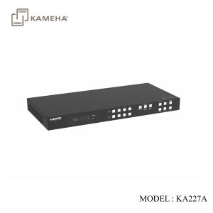
The 18Gbps 4×4 Seamless Matrix is a perfect solution for video transmission from 4 HDMI sources to 4 HDTV displays. It has video wall and multi-viewer functions with multiple display modes. 4×4 IR matrix, audio embedded and de-embedded are also supported. Video resolution is up to 4K@60Hz 4:4:4. Each of the sources can be individually scaled. And seamless switching ensures a smooth picture transition without frame loss. This matrix can be controlled via front panel buttons, IR remote, RS-232 and Web GUI.
Features
- HDCP 2.2 compliant
- Support video resolution up to 4K@60Hz 4:4:4and 18Gbps video bandwidth, as specified in HDMI 2.0
- Support 12 display categories in multi-viewer mode, and 9 splicing modes in video wall mode
- HDMI audio format: LPCM, Dolby Digital/Plus/EX, Dolby True HD, DTS, DTS-EX, DTS-96/24, DTS High Res, DTS-HD Master Audio
- Support CEC control, and multiple video resolution output
- Advanced EDID management
- Control via front panel buttons, IR remote, RS-232, and Web GUI
Specifications
| Technical | |||
| HDMI Compliance | HDMI 2.0 | ||
| HDCP Compliance | HDCP 2.2 | ||
| Video Bandwidth | 594MHz/18Gbps | ||
| Video Resolution | 480i ~1080P@50/60Hz, 4K2K@24/30Hz, 4K2K@60Hz | ||
| Colour Space | RGB, YCbCr 4:4:4, YCbCr 4:2:2, YCbCr 4:2:0 | ||
| Colour Depth | 8/10/12-bit | ||
| Audio Formats | LPCM, Dolby Digital/Plus/EX, Dolby True HD, DTS, DTS-EX, DTS96/24, DTS High Res, DTS-HD Master Audio | ||
| IR Level | 12Vp-p | ||
| IR Frequency | Wideband 20K-60KHz | ||
| ESD Protection | IEC 61000-4-2: ±8kV (Air-gap discharge) & ±4kV (Contact discharge) | ||
| Connection | |||
| Input ports | 4 × HDMI INPUT [Type A, 19-pin female]
4 × L/R AUDIO INPUT [3.81mm, 3pin Phoenix Connector] |
||
| Output ports | 4 × HDMI OUTPUT [Type A, 19-pin female]
4 × OPTICAL AUDIO OUT [S/PDIF] 4 × L/R AUDIO OUT [3.81mm, 5pin Phoenix Connector] |
||
| Control ports | 1 × TCP/IP [RJ45]
1 × RS-232 [D-Sub 9] 1 × IR EXT [3.5mm, Stereo Mini jack] 4 × IR INPUT [3.5mm, Stereo Mini jack] 4 × IR OUTPUT [3.5mm, Stereo Mini jack] |
||
| Mechanical | |||
| Housing | Metal Enclosure | ||
| Color | Black | ||
| Dimensions | 440mm [W] × 203mm [D] × 44.5mm [H] | ||
| Weight | 2.55kg | ||
| Power Supply | Input: AC 100-240V 50/60Hz, Output: DC 12V/2.5A
(US/EU standard, CE/FCC/UL certified) |
||
| Power Consumption | 25W (Max) | ||
| Operating Temperature | 32 – 104°F / 0 – 40°C | ||
| Storage Temperature | -4 – 140°F / -20 – 60°C | ||
| Relative Humidity | 20 – 90% RH (no-condensing) | ||
| Video Resolution | 4K60 | 4K30 | 1080P60 |
| HDMI Cable Length (HDMI IN / OUT) | 5m/16ft | 10m/32ft | 15m/50ft |
| The use of “Premium High-Speed HDMI” cable is highly recommended. | |||
Operation Controls and Functions
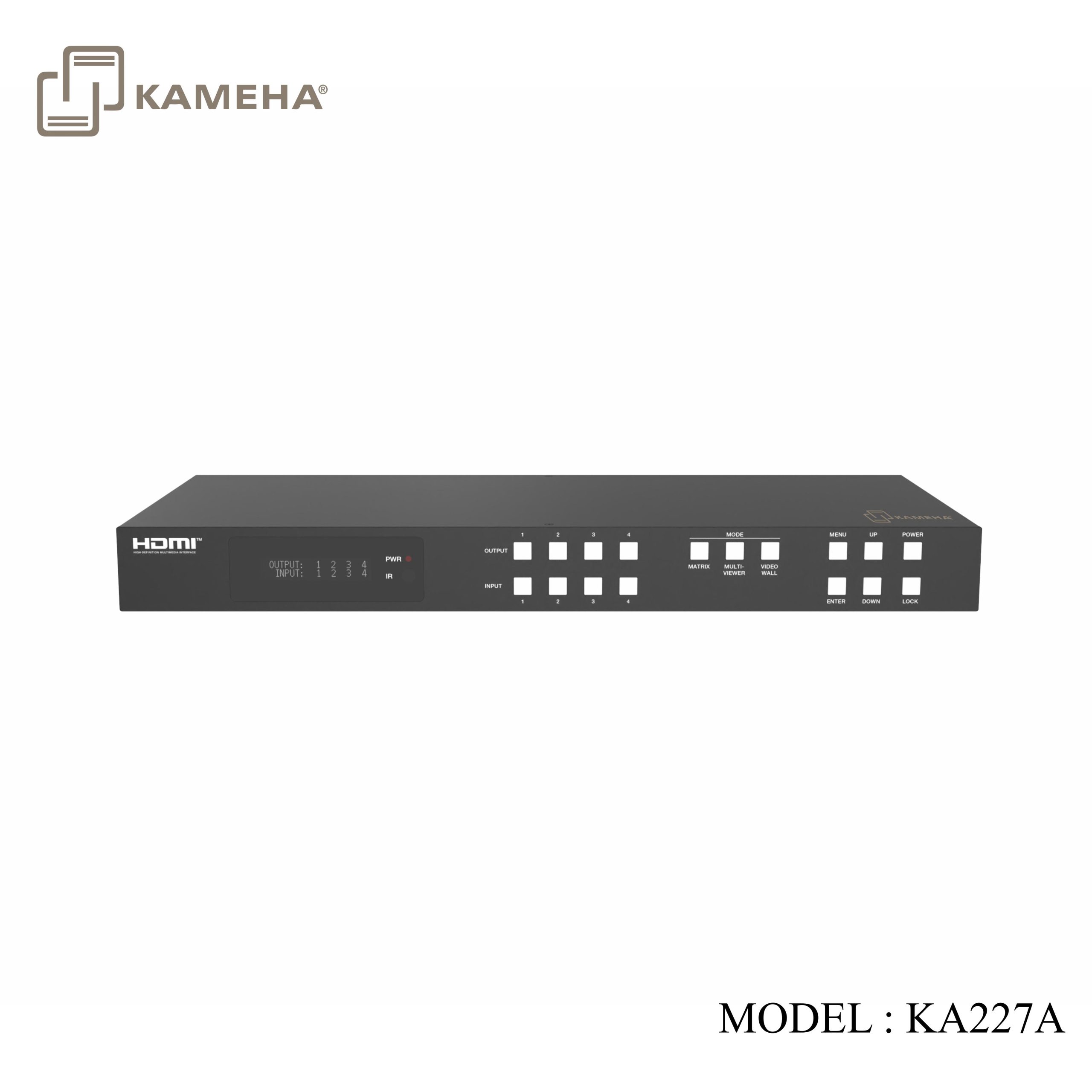
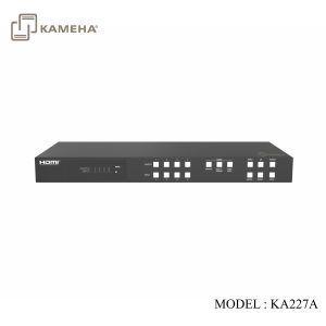
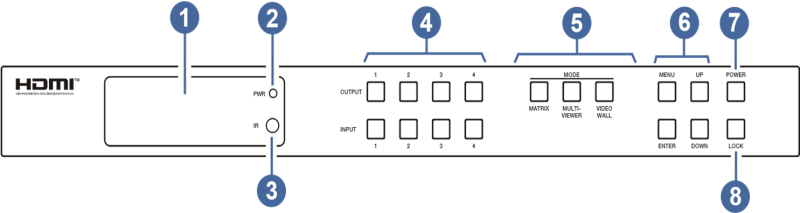
Front Panel
| NO. | Name | Function Description |
| 1 | LCD screen | Display matrix switching status, input / output port, EDID, Baud rate, IP Address, etc. |
| 2 | PWR LED | The LED is on green when the device is working. The LED is on red when the device is on standby. |
| 3 | IR | IR signal receiver, receiving the signal from the IR remote. |
| 4 | INPUT / OUTPUT buttons | You need to press an output button (1~4) firstly and then press an input button (1~4) to select the corresponding input source for the output port. |
| 5 | MODE
(MATRIX / MULTIVIEWER / VIDEO WALL) |
Press these buttons to select the corresponding video mode as required. MATRIX: Press Matrix button to enter the matrix mode. You can operate via front panel buttons, RS-232 commands and Web GUI to set more details of the matrix mode.
MULTIVIEWER: Press MULTIVIEWER button to enter the multi-viewer mode (The output buttons are used as Windows). You can operate via front panel buttons, RS-232 commands and Web GUI to set more details of the multi-viewer mode. VIDEO WALL: Press VIDEO WALL button to enter the video wall mode (The output buttons are used as Groups). You can operate via front panel buttons, RS-232 commands and Web GUI to set more details of the video wall mode. |
| 6 | MENU / ENTER / UP / DOWN | Take RESET, for example.
1. On the initial LCD display screen, press “MENU” button. There are OUTPUT/MV/VW/INPUT/EXTAUDIO/SET items to be selected. 2. Press the “UP/DOWN” button to select “SET” item. 3. Press the “ENTER” button to enter into the next level menu. There are LCD ONTIME/BAUD RATE/IP INFO/BG PATTERN/REBOOT/ RESET items to be selected. 4. Press the “UP/DOWN” button to select “RESET” item. 5. Press the “ENTER” button to confirm the selection. 6. Press the “ENTER” button, and then it will prompt: SUCCESS! Note: · Pressing the “MENU” button will return to the previous menu. · In any level menu, it will return to the initial display screen if no operation goes on within 10 seconds. |
| 7 | POWER button | Long press the button for 1 second to enter the standby mode, then short press it to wake up the device. |
| 8 | LOCK button | Short press the button to lock front panel buttons (Except the power button); press it again to unlock. |
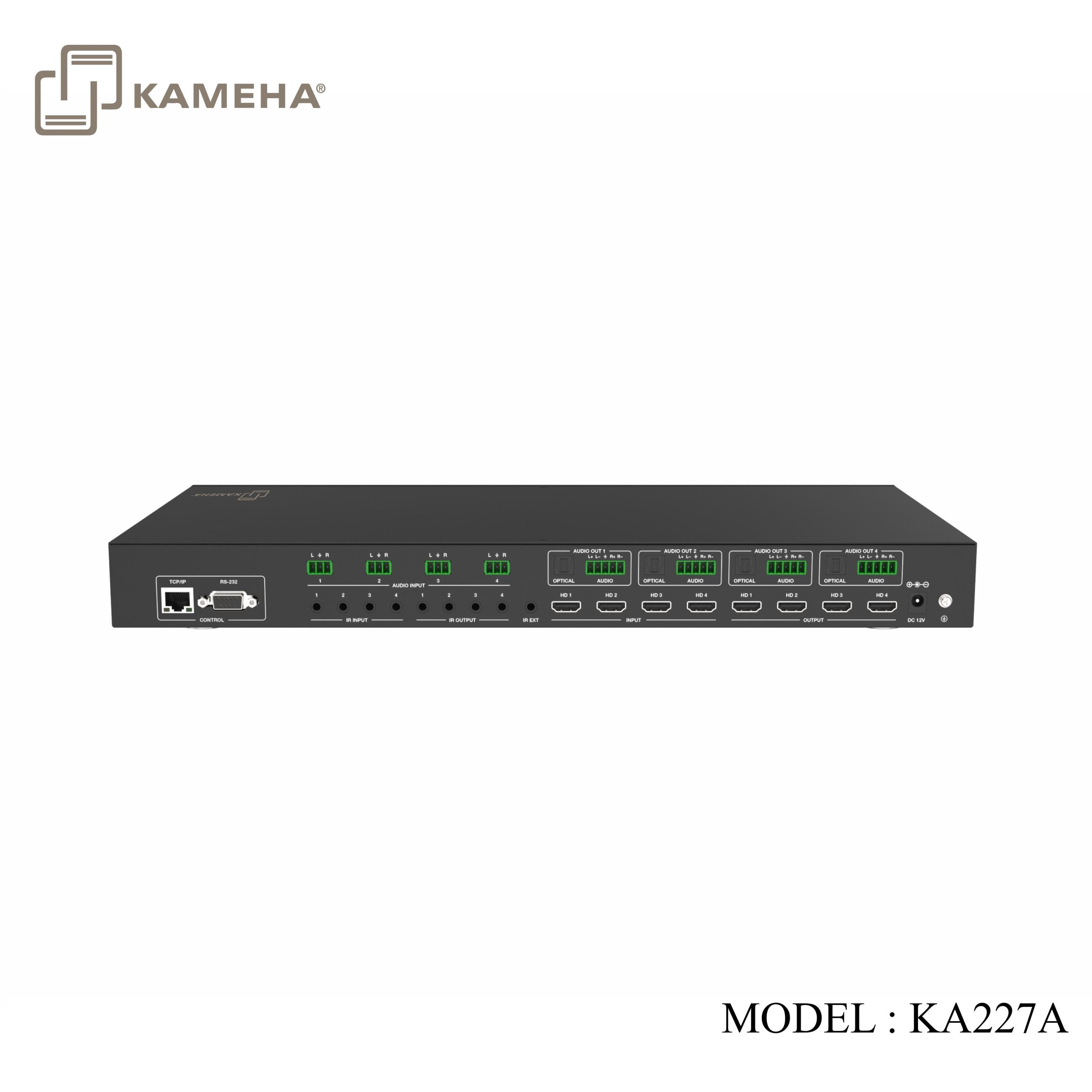
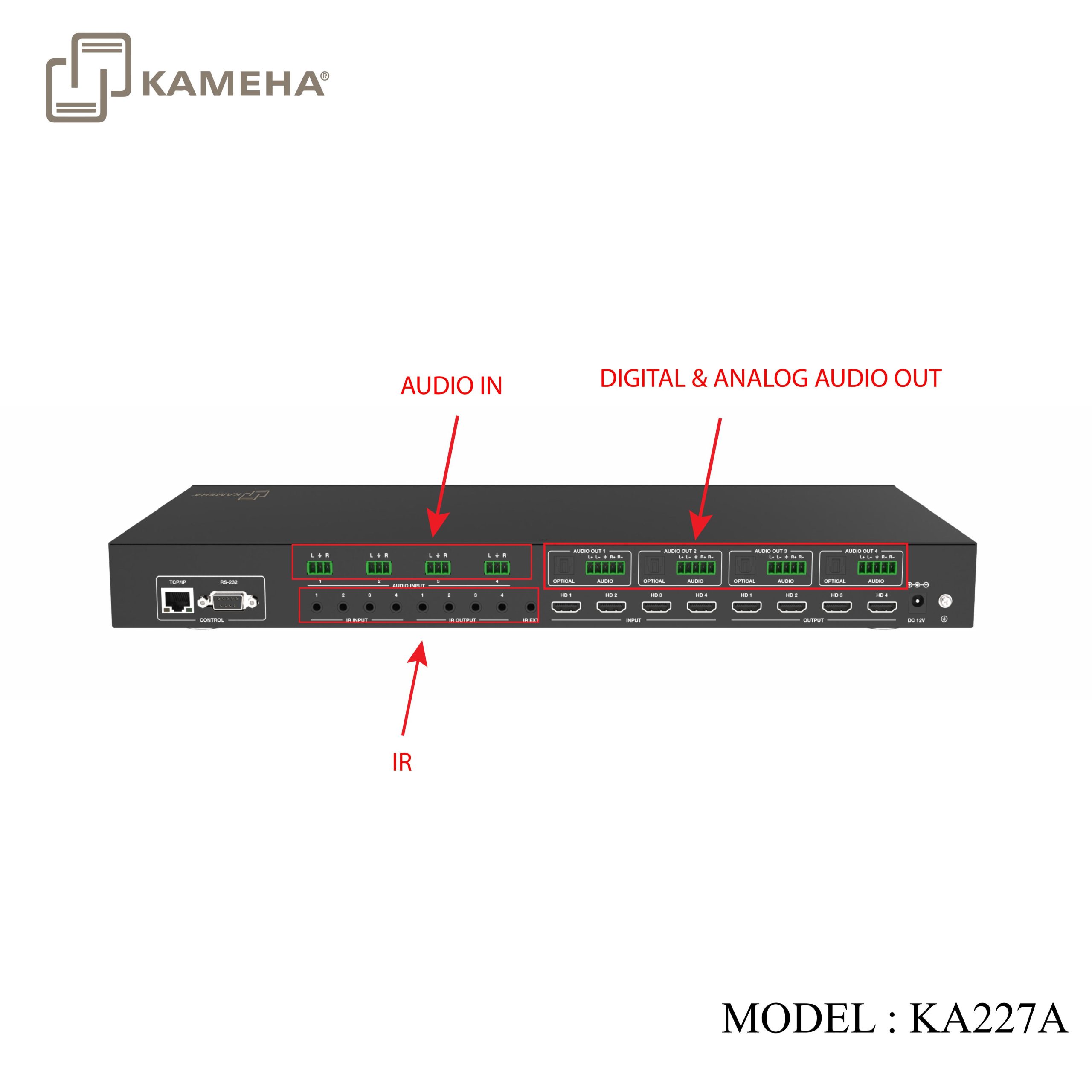
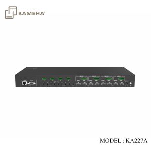
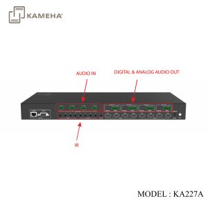
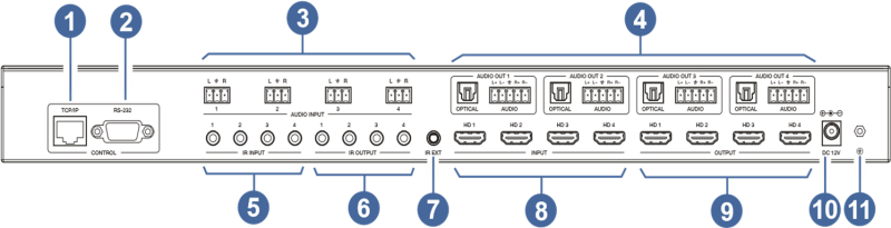
Rear Panel
| NO. | Name | Function Description |
| 1 | TCP/IP | TCP/IP control port, connected to PC or router with a CAT cable. |
| 2 | RS-232 port | Connect to a PC or control system by D-Sub 9-pin cable to transmit RS-232 command. |
| 3 | AUDIO INPUT (1~4) | L/R analogue audio input port, connected to an analogue audio input source such as DVD or Blu-ray Player. It follows HDMI input (1~4), and the embedded audio cannot be extracted to audio out channel to output. |
| 4 | AUDIO OUT
(1~4) |
OPTICAL: Optical audio output port, connected to an audio output device such as audio amplifier. |
| L/R AUDIO: Analog audio output port, supporting balanced audio output (with a maximum support of 2Vrms) and unbalanced audio output. Balanced connection method: L+, L -, , R+, RUnbalanced connection method: L+, , R+ | ||
| 5 | IR INPUT (1~4) | Connect with IR receiver cable. |
| 6 | IR OUTPUT
(1~4) |
Connect with IR blaster cable. |
| 7 | IR EXT | If the IR receiver window of the unit is blocked or the unit is installed in a closed area out of infrared line of sight, the IR receiver cable can be connected to the “IR EXT” port to receive the IR remote signal. |
| 8 | HDMI INPUT ports (1~4) | HDMI input ports, connected to HDMI source devices such as computer, DVD or set-top box with an HDMI cable. |
| 9 | HDMI OUTPUT
ports (1~4) |
HDMI output ports, connected to HDMI display devices such as TV or monitor with an HDMI cable. |
| 10 | DC 12V | Connect to 12V/2.5A power adapter. |
| 11 | GND | Connect the housing to the ground. |
IR Remote
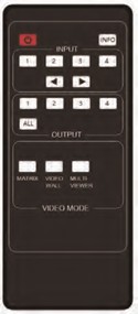
![]() : Power on the Matrix or set it to standby mode.
: Power on the Matrix or set it to standby mode.
INFO: Press to check the serial baud rate and IP address. It will be displayed in the top right corner of the screen,
and disappear in five seconds or press the button again.
INPUT 1/2/3/4: Press these buttons to select input sources.
◄ ►: Select the last or next input source.
OUTPUT 1/2/3/4: Select the output display device.
ALL: Select all output simultaneously. For example, when you press the “ALL” button and then press input “1” button, at this time the input “1” source will be output to all display devices.
NOTE :
1. Multiviewer and video wall do not function simultaneously.
2. Setting Port 1 to Multiviewer, Ports 2, 3, and 4 will also automatically switch to Multiviewer.
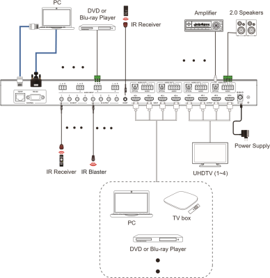
Application Example

Additional information
| Weight | 4.10 kg |
|---|---|
| Dimensions | 55.00 × 32.00 × 12.00 cm |
| Warranty | 1 year warranty |
| WHAT'S IN THE BOX | 1* 18Gbps 4×4 Seamless Matrix |
Related products