
Description
Introduction
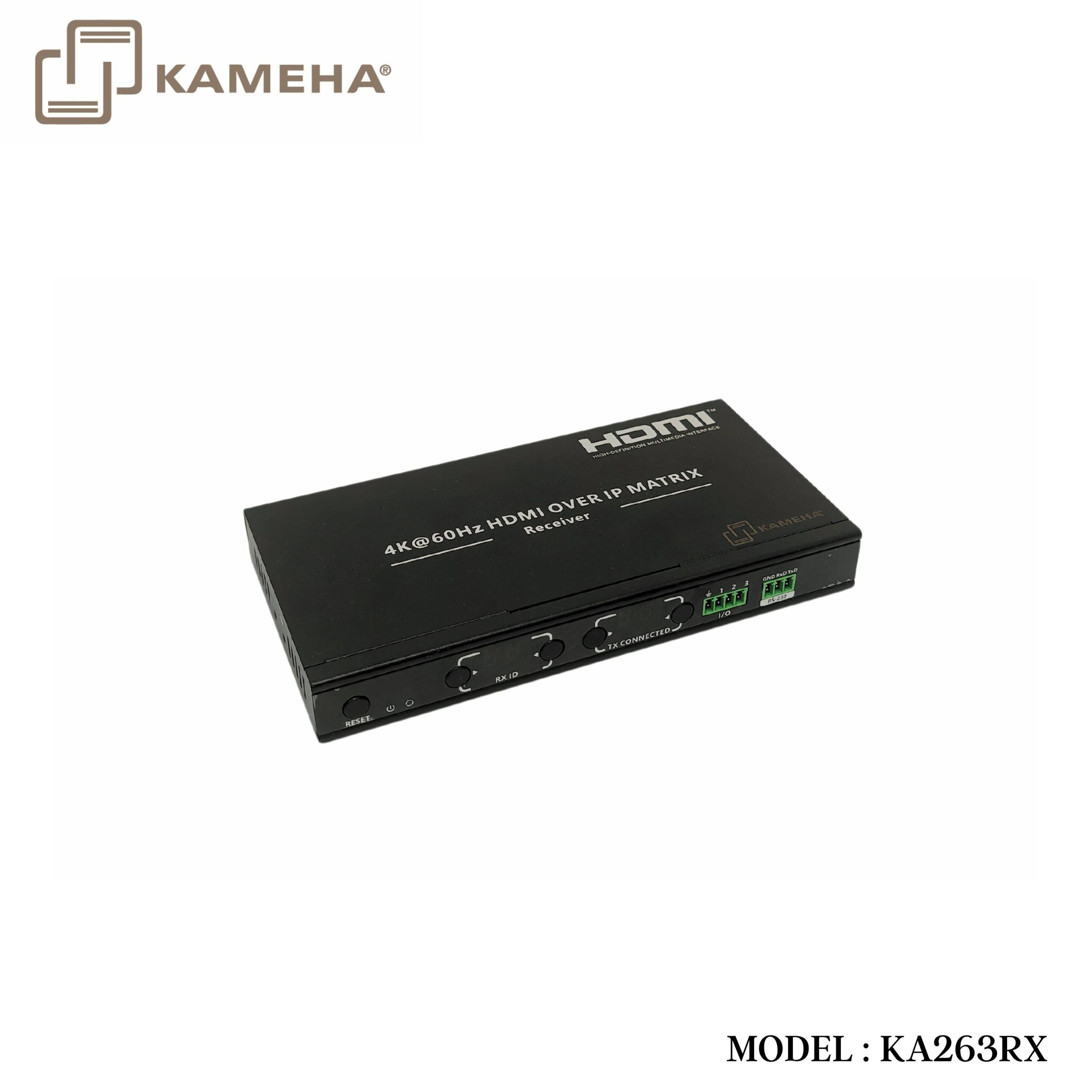
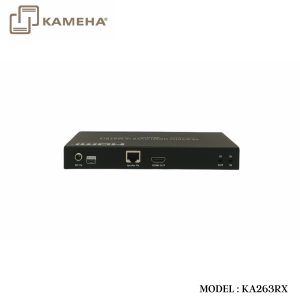
This 4K@60Hz HDMI over IP matrix kit, including a transmitter and a receiver, realizing switching, extending and distributing 4K@60Hz audio and video signals via the IGMP switch. Built on ipcolor STREAM™ technology to deliver high-definition and low-latency transmission. The transmitter can extend 100 signal sources and switch to 253 receiving terminals. The HDMI signal can be extended up to 120 meters over Category 6 or higher-level networking cables while supporting one-toone connection and many-to-many connection. Equipped with HDMI loop out, bi-directional IR passback, RS-232 command control, I/O. Widely used in audiovisual conference, transportation control center, radio and television, education and training and other fields.
Features
- Built on ipcolor STREAM™ technology to deliver high-definition and low-latency transmission.
- Supports up to 3840 x 2160@60Hz resolution, backwards compatible.
- Compatible with Cat5/5e/6 or higher-level networking cables, transmission distance of Cat6 cable is 120 meters.
- Supports one-to-one or many-to-many connections through the gigabit switch.
- Supports RS-232 passthrough and control.
- The transmitter supports HDMI loop out.
- Supports bi-directional IR pass-back(20~60KHz).
- Supports I/O interface control.
- Supports POE (Power over Ethernet).
- Creating multi-screen splicing with up to 5×5(also include 1×1/1×2/1×3/1×4/1×5/2×1/2×2/2×3/2×4/2×5/3×1/3×2/3×3/3×4/3×5/4×1/4×2/4×3/4×4/4×5/5×1/ 5×2/5×3/5×4/5×5) video wall through switch and controlled by APP.
- Supports 100 signal source inputs and 253 signal outputs, providing flexible many-to-many matrix configuration.
- Firmware upgrading via Micro USB port.
- Lightning protection, surge protection, ESD protection.
- Supports stable 24/7 operation.
Technical Parameter
| Item | Transmitter | Receiver |
| Video | ||
| Input interface | 1x HDMI | 1x RJ45 |
| Output interface | 1xHDMI 1xRJ45 |
1x HDMI
|
| HDMI Length | ≤5m | ≤5m |
| Maximum transfer rate | 18Gbps | |
| Compatibility | HDMI 2.0 | |
| HDCP 1.4/HDCP 2.2 | ||
| Resolution | 3840×2160@24/30/50/60Hz, 1080P@50/60Hz, 720@50/60Hz, 1920×1200@60Hz, 2560×1440@60Hz | |
| Connection types | One-to-one connection, Many-to-many connection, Switch cascading | |
| Transmission distance | CAT5 80m/ CAT5E 100m/ CAT6 100m | |
| Transmission latency | 70~180ms | |
| Audio signal | ||
| Input interface | 1x HDMI | 1x RJ45 |
| Output interface | 1x HDMI 1x RJ45 |
1x HDMI
|
| HDMI output | LPCM 2.0 | |
| Command Signal | ||
| Input Interface | 1x 3.5mm IR input 1x 3.5mm IR output |
1x 3.5mm IR input 1x 3.5mm IR output |
| IR receiving range | ≤5m | |
| IR frequency | 20kHz~60kHz | |
| RS232 (GND/RXD/TXD) | Default baud rate: 115200 Supported: 2400, 8400, 9600, 19200, 38400, 57600, 115200 |
|
| Power | ||
| Power supply | DC 5V/2A | DC 5V/2A |
| Power Consumption | TX ≤ 5.5W | RX ≤ 3.5W |
| Operating Environment | ||
| Working Temperature | -20°C ~ 60°C | |
| Storage Temperature | -30°C ~ 70°C | |
| Humidity | 0 ~ 90%RH (no condensation) | |
| Physical Properties | ||
| Housing | Iron | |
| Weight | 472g | 458g |
| Color | Black | |
| Dimensions | 191(L) * 96(W) * 25(H) mm | |
| Protection | ESD protection 1a Contact discharge level 2 (±4KV) 1b Air discharge level 3 (±8KV) Implementation of the standard: IEC61000-4-2 |
|
| Lightning protection, Surge protection | ||
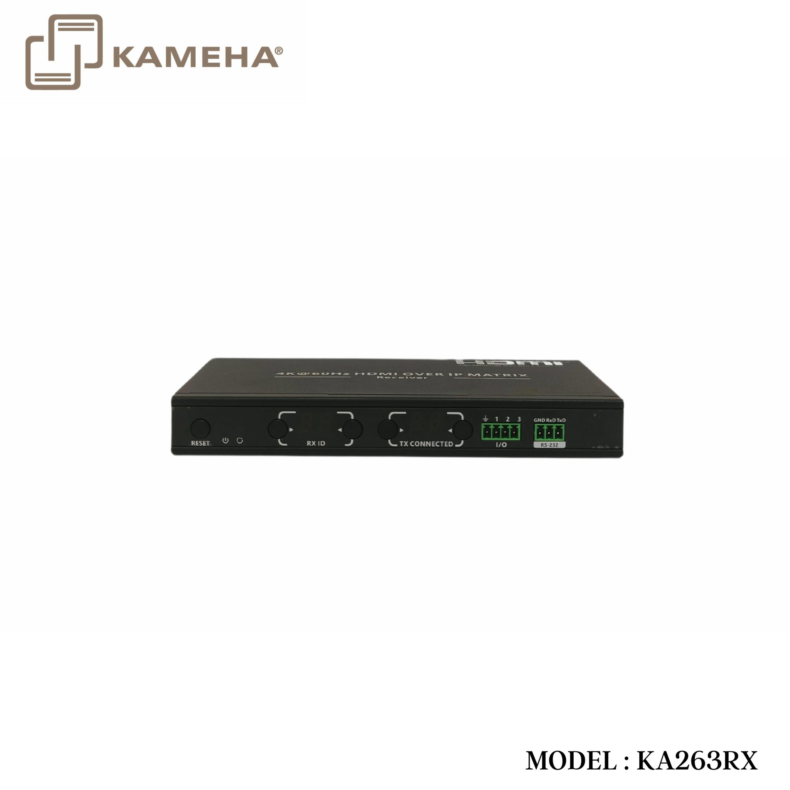
Panel Description
Receiver
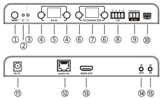
| 1. | Reset | 1)Press to restart the device
2)Press and hold for 5 seconds to restore factory settings |
| 2. | Power indicator (blue) | The indicator will turn on when the power is turned on |
| 3. | Status indicator (orange) | 1)Light off: The transmitter and the receiver have not established a connection
2)Flash: The transmitter and the receiver are connected but no video data transmission 3)Steady on: The video data is transmitting |
| 4. | Receiver ID setting button | Set up the ID of the receiver |
| 5. | Receiver ID indicator | Indicate the ID of the receiver |
| 6. | Transmitter connected ID setting button | Set the ID of the transmitter connected |
| 7. | Transmitter connected ID indicator | Indicator the ID of the transmitter connected |
| 8. | I/O interface | Use the terminal block to connect the external device, and control the input/output signal via the control APP |
| 9. | RS-232 (GND/RXD/TXD) | 1)RS-232 passthrough commands for TX/RX
2)RS-232 control commands for APP |
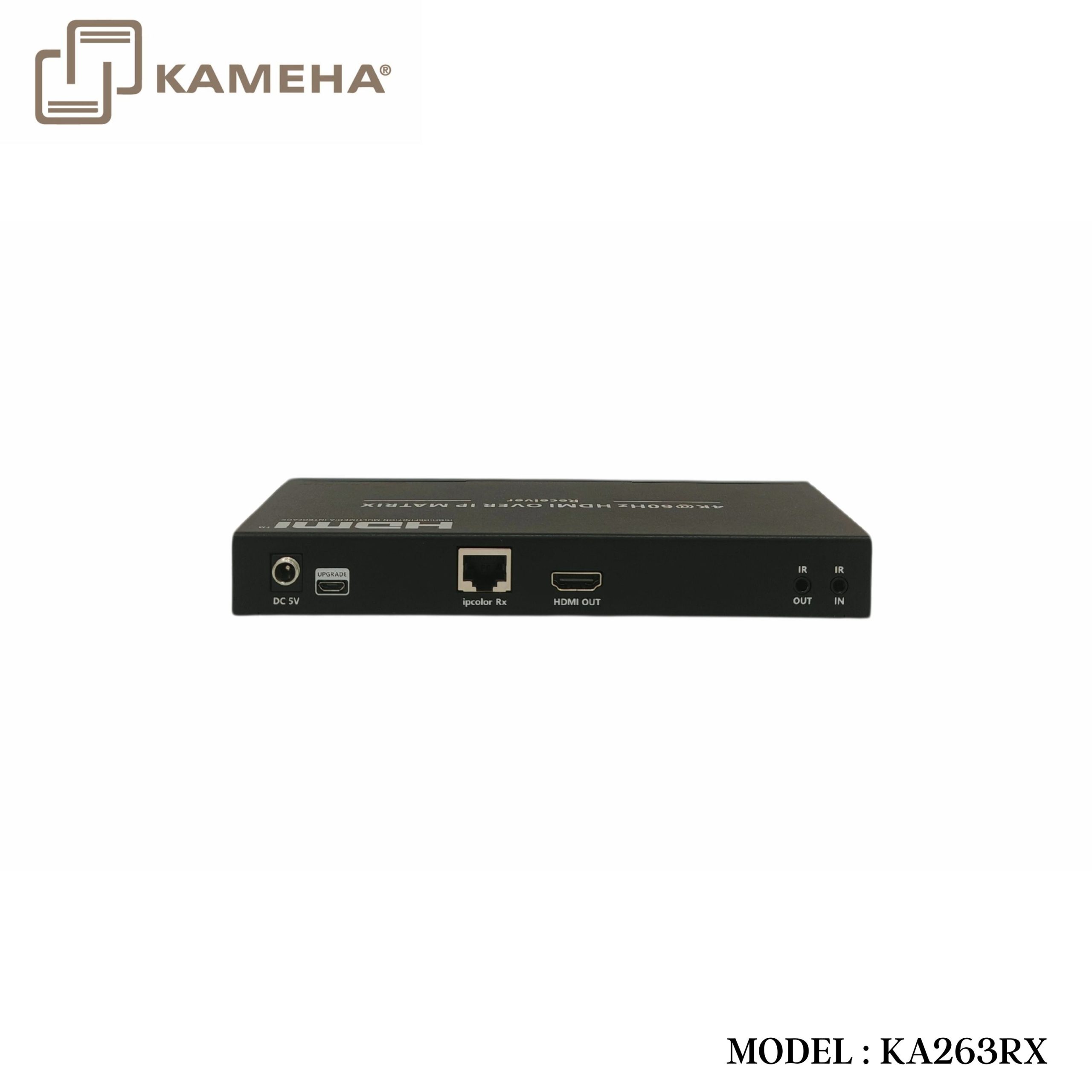
| 10. | Micro USB port | For firmware upgrading |
| 11. | Power | Connect with DC5V/2A power adapter |
| 12. | Ipcolor TX | Connect with CAT5/5e/6 or higher-level networking cables (POE input) |
| 13. | HDMI output | Connect with HDMI display device |
| 14. | IR output | Connect with IR blaster extension cable |
| 15. | IR input | Connect with IR receiver extension cable |
Connection Diagrams
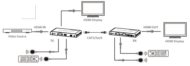
- One-to-one connection
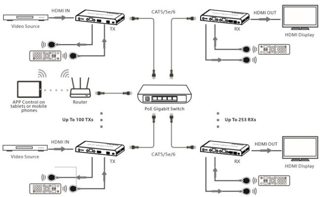
- Many-to-many connection (through gigabit switch)
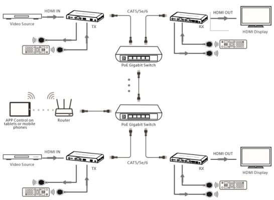
- Many-to-many switch cascade connection (through gigabit switch)
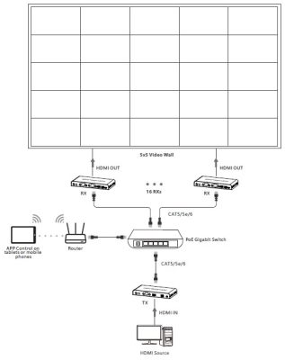
- Creating multi-screen splicing with up to 4×4 video wall through switch and controlled by APP
Additional information
| Weight | 0.80 kg |
|---|---|
| Dimensions | 23.70 × 21.50 × 8.00 cm |
| WARRANTY | 1 YEAR WARRANTY |
| WHAT'S IN THE BOX | 1* 4K HDMI Over IP Matrix Extender Receiver |
Related products


