


Description
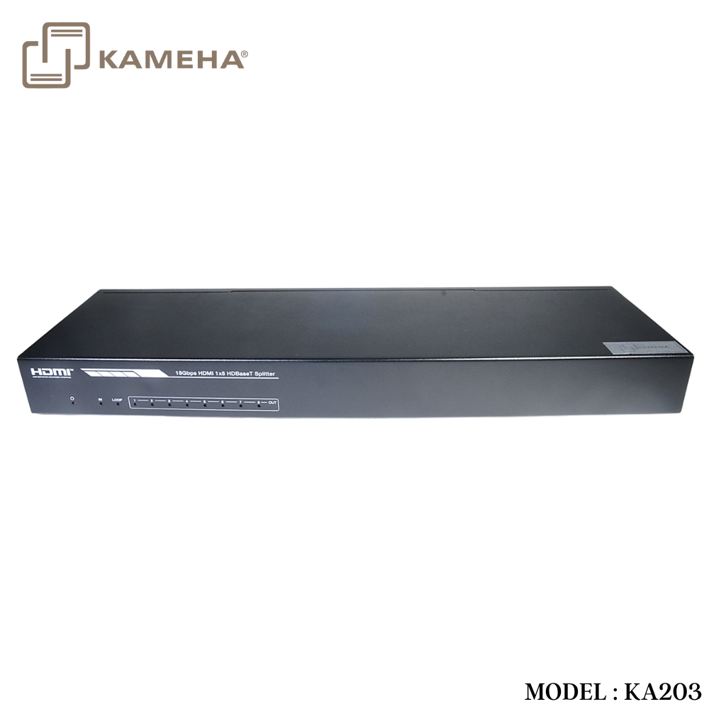
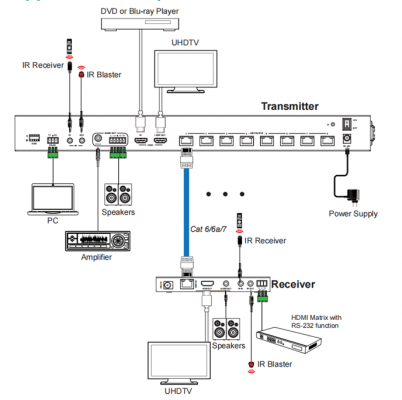
This 18Gbps HDMI 1×8 HDBaseT Splitter can distribute 1 source signal to any 8 display devices. Support video resolution up to 4K2K@60Hz 4:4:4. It is designed with 1 HDMI loop output and 8 HDBaseT outputs. The HDMI signal transmission distance can be extended up to 120 meters at the resolution of 4K2K@60Hz, or 150 meters at 1080P@60Hz via a single CAT6/ 6a/7 cable. The product supports IR and RS-232 signal pass-through, audio extract function and advanced EDID management.
Features
- HDMI 2.0b, HDCP 2.2 and HDCP 1.x compliant
- Support 18Gbps video bandwidth
- Support video resolution up to 4K2K@60Hz 4:4:4
- Support HDR, HDR10+, HLG and Dolby vision
- Support up to 7.1CH HD audio pass-through
- Support digital and analog audio de-embedded output
- Extend the signal transmission distance up to 120 meters at the resolution of 4K2K@60Hz, 150 meters at 1080P@60Hz via a single CAT6/6a/7 cable
- Support 1 HDMI input, 1 HDMI loop output and 8 HDBaseT outputs.
- IR, RS-232 routed to HDBaseT output
- Advanced EDID management
- Support one-way POC function (only from transmitter to receiver)
- Compact design for easy and flexible installation
Specifications
| Technical | |
| HDMI Compliance | HDMI 2.0b |
| HDCP Compliance | HDCP 2.2/1.x |
| Video Bandwidth | 594MHz/18Gbps |
| Video Resolution | Up to 4k2k@60Hz 4:4:4 |
|
Color Depth |
8-bit,10-bit,12-bit(1080p@60Hz) 8-bit (4K2K@60Hz YUV4:4:4)
8-bit,10-bit,12-bit(4K2K@60Hz YCbCr 4:2:2/4:2:0) |
| Color Space | RGB 4:4:4, YCbCr 4:4:4 / 4:2:2 / 4:2:0 |
| HDR | Support HDR, HDR10+, HLG, Dolby vision |
| HDMI Audio Formats | LPCM 2.0/2.1/5.1/6.1/7.1, Dolby Digital, Dolby TrueHD, Dolby Digital Plus(DD+), DTS-ES, DTS HD Master, DTS HD-HRA, DTS-X |
| Coaxial Audio Formats | PCM2.0, Dolby Digital / Plus, DTS 2.0/5.1 |
| Analog Audio Formats | PCM 2.0CH |
| ESD Protection | Human body model—±8kV (Air-gap discharge) &
±4kV (Contact discharge) |
| Connection | |
| Input | 1×HDMI Type A (19-pin female) |
| Output | 1×HDMI Type A (19-pin female) 8x HDBaseT OUT [RJ45]
1x Coaxial Audio OUT [RCA] 1x L/R Audio OUT [5-pin phoenix connector] |
| Control | 1×RS-232 (3-pin phoenix connector) 1x EDID DIP switch [5-pin]
1x IR IN [3.5mm Stereo Mini-jack] 1x IR OUT [3.5mm Stereo Mini-jack] |
| Mechanical | |
| Housing | Metal Enclosure |
| Silkscreen Color | Black |
| Dimensions | Transmitter: 440mm (W) × 130mm (D) × 44mm (H) Receiver: 140mm (W) × 65mm (D) × 18mm (H) |
| Weight | Transmitter: 1.62kg Receiver: 246g |
| Power Supply | Input: AC100 – 240V 50/60Hz, Output: DC 24V/3.75A
(US/EU standards, CE/FCC/UL certified) |
| Power Consumption | 72W |
| Operation
Temperature |
0°C ~ 40°C / 32°F ~ 104°F |
| Storage Temperature | -20°C ~ 60°C / -4°F ~ 140°F |
| Relative Humidity | 20~90% RH (non-condensing) |
Operation Controls and Functions
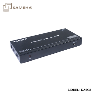
Transmitter
Front Panel
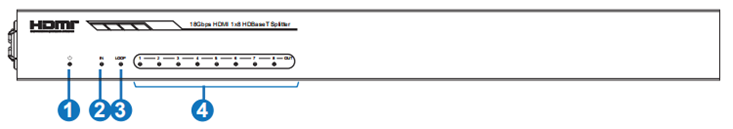
| No. | Name | Function Description |
| 1 | POWER LED | When the device is powered on, the red power LED will be on. |
| 2 | IN LED | When the HDMI IN port connects an active source device, the green LED will be on. |
| 3 | LOOP LED | When the HDMI LOOP OUT port connects an active display device, the green LED will be on. |
| 4 | OUT(1~8) LED | When the HDBT OUTPUT port connects an HDBaseT Receiver, the corresponding green OUT LED will be on. |
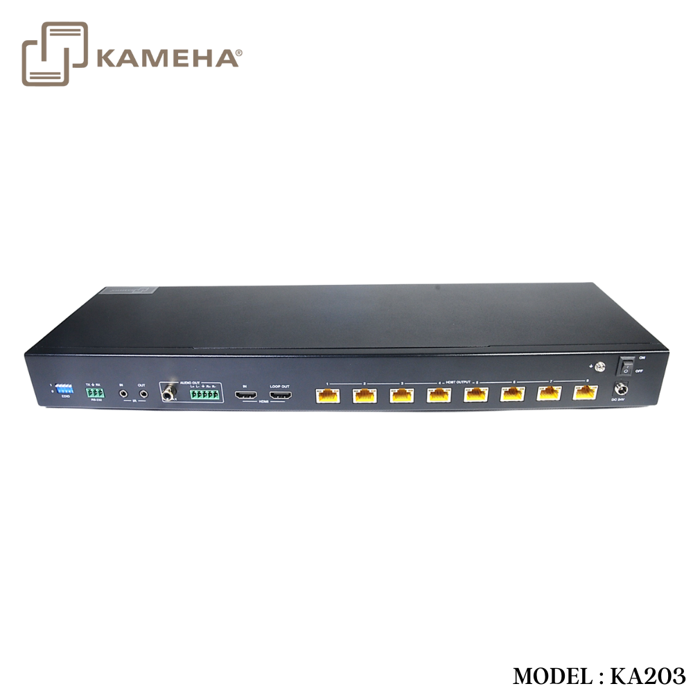
Rear Panel

| No. Name | Function Description | |
| 1 | EDID DIP
switch |
Used to set EDID mode. Please refer to Section “6. EDID Mode” for details. |
|
2 |
RS-232 |
Connect to a PC or control system via a 3-pin phoenix connector cable for three functions:
1, Firmware update; 2, Control the Splitter via RS-232 commands; 3, RS-232 signal pass-through (from transmitter to receiver or from receiver to transmitter). |
| 3 | IR IN | Connect to IR receiver cable, the IR receive signal will emit to “IR OUT” port of the HDBaseT Receiver. |
| 4 | IR OUT | Connect to IR blaster cable, the IR emit signal is from “IR IN” port of the HDBaseT Receiver. |
| 5 | AUDIO OUT
(COAX, L/R) |
Coaxial/balanced audio output port, connect to amplifier or speaker. |
|
6 |
HDMI port |
IN: HDMI input port, connect to HDMI source device such
as DVD or set-top box with an HDMI cable. LOOP OUT: HDMI loop output port, connect to the HDMI display device such as TV or Monitor with an HDMI cable. |
| 7 | HDBT OUTPUT
port (1~8) |
Connect to the HDBT IN port of the HDBaseT receiver
with a CAT cable. |
|
8 |
Connection Signal Indicator lamp (Green) |
▪ Illuminating: Transmitter and Receiver are in good connection status.
▪ Flashing: Transmitter and Receiver are in poor connection status. ▪ Dark: Transmitter and Receiver are not connected. |
|
9 |
Data Signal Indicator lamp
(Orange) |
▪ Illuminating: HDMI signal with HDCP.
▪ Flashing: HDMI signal without HDCP. ▪ Dark: No HDMI signal. |
|
10 |
DC 24V |
Plug the DC 24V power supply into the unit and connect the adaptor to an AC outlet. (Note: The transmitter can power the receiver via a CAT cable.) |
| 11 | POWER switch Press this switch to power on/off the device. | |
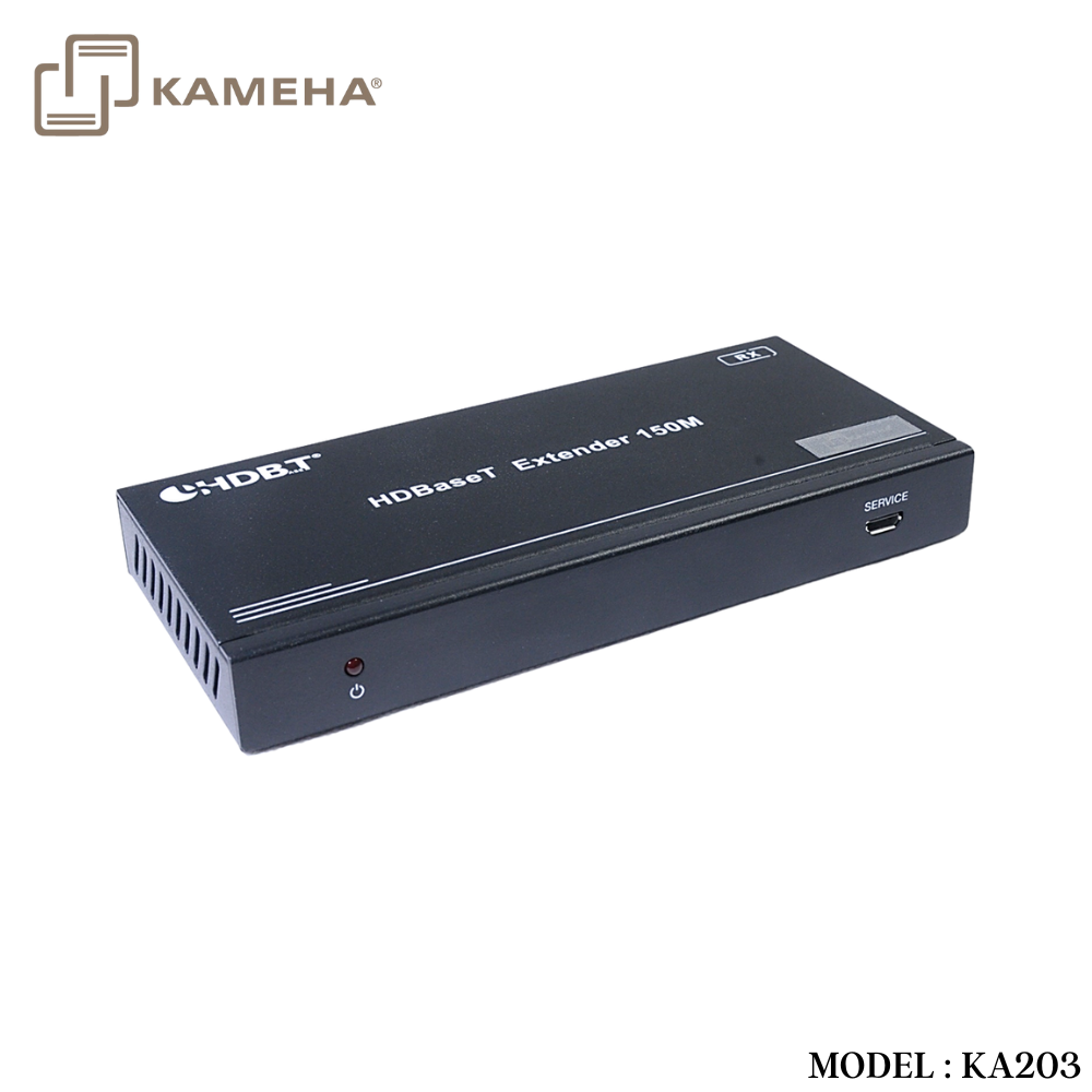
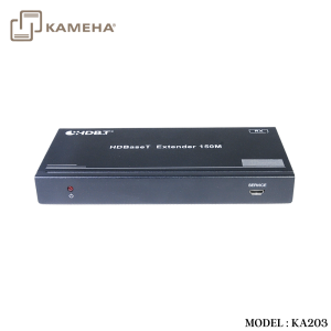
HDBaseT Receiver

| No. | Name | Function Description |
| 1 | Power Indicator | When the receiver is powered on, the power indicator will be on. |
| 2 | SERVICE port | Used for firmware update. |
|
3 |
DC 24V |
Plug DC 24V/1A power supply into the unit and connect
the adapter to an AC outlet. (Note: The HDBaseT receiver also can be powered by the transmitter via a CAT cable.) |
| 4 | HDBT IN | Connect to the HDBT OUTPUT port on the transmitter
with a CAT cable. |
|
5 |
Connection Signal Indicator lamp (Green) |
▪ Illuminating: Transmitter and Receiver are in good connection status.
▪ Flashing: Transmitter and Receiver are in poor connection status. ▪ Dark: Transmitter and Receiver are not connected. |
|
6 |
Data Signal Indicator lamp
(Orange) |
▪ Illuminating: HDMI signal with HDCP.
▪ Flashing: HDMI signal without HDCP. ▪ Dark: No HDMI signal. |
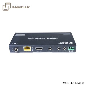
| 7 | HDMI OUT | HDMI output port, connect to HDMI display device such as TV or Projector with an HDMI cable. |
| 8 | AUDIO OUT | Audio output port, connect to amplifier or speaker. |
| 9 | IR IN | Connect to the IR Receiver cable. The IR signal will send to the IR OUT port of the transmitter. |
| 10 | IR OUT | Connect to the IR blaster cable, the IR signal is from IR
IN port of the transmitter. |
|
11 |
RS-232 |
3-pin Phoenix connector for RS-232 command transmission. The RS-232 command will pass-through from transmitter to receiver or from receiver to transmitter. |
Application Example
Additional information
| Weight | 5.60 kg |
|---|---|
| Dimensions | 51.50 × 33.50 × 11.00 cm |
| WARRANTY | 1 YEAR WARRANTY |
| WHAT'S IN THE BOX | 1 × 18Gbps HDMI 1×8 HDBaseT Splitter |
Related products