


Description
The product is a multi-function AV intelligent education system. It offers 2HDMI and VGA video extension, video switching, system control and analog audio amplification. Uncompressed video and audio can be transmitted up to 230ft/70m. This design of HDBaseT™ technology allows for full usage of HDMI and controls over CAT5e/6/6A cable. The product supports Web GUI and panel button control.
Transmitter support HDCP 1.4, HDCP2.2 and can be switched manually, auto, hybrid or priority. And the maximum distance can be up to 70m at 1920×1200@60Hz or up to 40m at 4K @ 30 Hz.
Receiver support a microphone input, analog audio output, 2×30 at 4 ohms speaker output, and Relay control to the projector screen rise and fall or RS-232 control to the display power on and off. A USB port on the receiver will transmit interactive display connections to the transmitter.
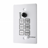
Control Panel supports volume control and system control. At the same time, it can support 2 HDMI and one VGA input selection.
Features
- HDMI 1.4b, HDCP 2.2 and HDCP 1.4 compliant.
- Video resolutions up to 4K2K@30Hz, 1080p@120Hz and 1080P 3D@60Hz.
- Audio up to 7.1 channels of High Definition audio pass through (LPCM, Dolby TrueHD, and DTS-HD Master Audio).
- HDBaseT™ over a single CAT5e/6/7 cable up to 230ft/70m distance.
- Support multi-VESA Standard VGA formats input.
- Supports MIC input.
- 2x30watts@4 ohms amplifier output.
- Supports interactive display USB pass-through.
- Supports Web GUI control.
- Supports control panel volume control and system control.
- Supports relay control.
- Supports RS-232 control.
Specifications
| Technical | |
| HDMI Compliance | HDMI 1.4 |
| HDCP Compliance | HDCP 2.2/HDCP 1.4 |
| Video Bandwidth | 10.2 Gbps |
| Video Resolution | up to 4K2K@30Hz,1080P@120Hz and 1080P 3D @60Hz |
| Color Space | RGB, YCbCr 4:4:4, YCbCr 4:2:2 |
| Color Depth | 8/10/12-bit |
| HDMI Audio Formats | LPCM 2/5.1/7.1CH, Dolby Digital, DTS 5.1, Dolby
Digital+, Dolby TrueHD, DTS-HD Master Audio, Dolby Atmos, DTS:X |
| ESD Protection | Human body model — ±8kV (Air-gap discharge) &
±4kV (Contact discharge) |
| Connections | |
| Transmitter | Inputs: 2x HDMI IN Type A [19-pin female]
1x VGA [DB15 VGA female] 1x AUDIO IN [3.5mm Stereo Mini-jack] 1x RS-232/POWER [RJ45] Outputs: 1x HDBaseT Out [RJ45] |
| Receiver | Inputs: 1x HDBaseT In [RJ45]
1x MIC IN [Screw Terminal] 1x USB [USB A TYPE] 1x TCP/IP [RJ45] Outputs: 1x HDMI OUT Type A [19-pin female] 1x RS-232 [Screw Terminal] 1x RELAY [Screw Terminal] 1x AUDIO OUT [Screw Terminal] 1x 2x30watts@4 ohms amplifier output [Screw Terminal] |
| Mechanical | |
| Housing | Metal Enclosure |
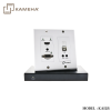
| Color | Transmitter: White, Receiver: Black |
| Dimensions | Transmitter:
115.9mm [W] x 114.3mm [D] x 38.7mm [H] Receiver: 250mm [W] x 104mm [D] x 30mm [H] |
| Weight | Transmitter: 305g, Receiver: 758g |
| Power Supply | Input: AC100 – 240V 50/60Hz, Output: DC 24V/3.75A
(US/EU standards, CE/FCC/UL certified) |
| Power Consumption | 75W (max) |
| Operating
Temperature |
32 – 104°F / 0 – 40°C |
| Storage Temperature | -4 – 140°F / -20 – 60°C |
| Relative Humidity | 20 – 90% RH (no condensation) |
Operation Controls and Functions
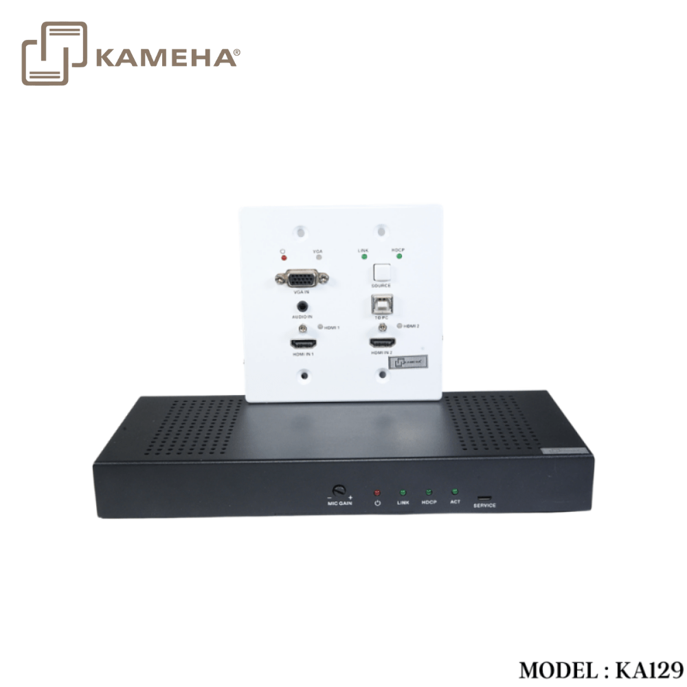
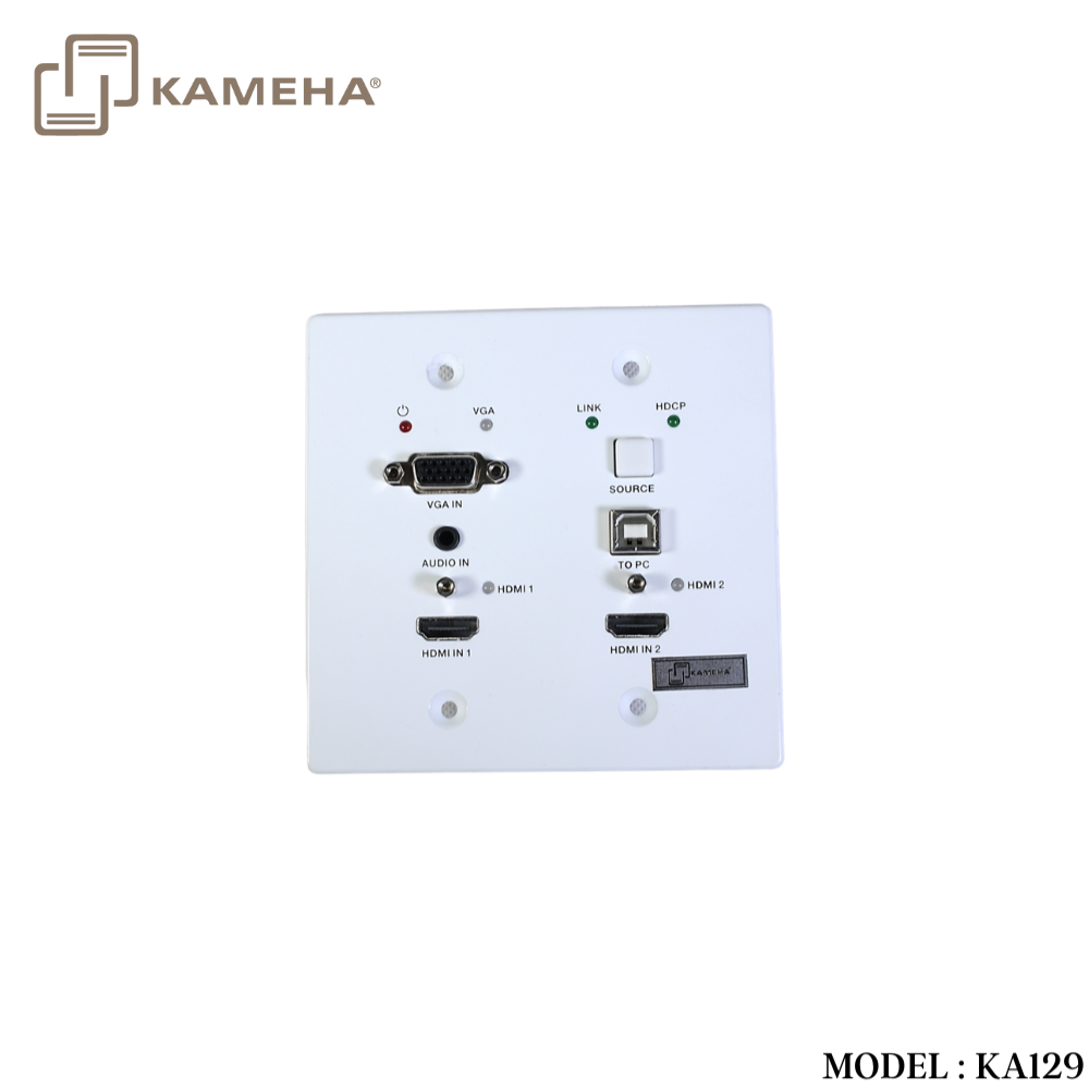
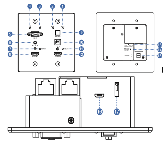
Transmitter Panel
| Number | Name | Function description | |
| 1 | HDCP LED | HDCP compliance indicator.
▪ OFF: HDMI input is not carrying HDCP content. ▪ ON: HDMI input is carrying HDCP content. |
|
| 2 | LINK LED | HDBaseT Link status indicator.
▪ OFF: No Link. ▪ GREEN: Link successful. ▪ Blink GREEN: Link abnormal. |
|
| 3 | VGA LED | VGA signal indicator.
▪ OFF: There is no +5V HPD or VGA signal detected on input. ▪ FLASHING: +5V HPD or VGA signal is detected. ▪ GREEN: VGA is active input and VGA signal is detected. |
|
| 4 | POWER LED | System power indicator. | |
| 5 | VGA IN | Connect to VGA source. | |
| 6 | ADUIO IN | Connect to external audio source for VGA signal. | |
| 7 | HDMI 1 LED | HDMI 1 signal indicator.
▪ OFF: There is no +5V HPD or HDMI signal detected on input. ▪ FLASHING: +5V HPD or HDMI signal is detected. ▪ GREEN: HDMI is active input and HDMI signal is detected. |
|
| 8 | HDMI 1 IN | Connect to HDMI source device. | |
| 9 | SOURCE | Press it to select one source. | |
| 10 | TO PC | Connect PC to transmit USB control signal from the Receiver USB device in. | |
| 11 | HDMI 2 LED | HDMI 2 signal indicator.
▪ OFF: There is no +5V HPD or HDMI signal detected on input ▪ FLASHING: +5V HPD or HDMI signal is detected. ▪ GREEN: HDMI is active input and HDMI signal is detected |
|
| 12 | HDMI 2 IN | Connect to HDMI source device. | |
| 13 | HDBaseT OUT | Connect to HDBaseT Receiver with a Cat5e/6/7 cable. | |
| 14 | RS-232/POWER | Connect to Control Panel via CAT5e/6/7 cable. | |
| 15 | 24VDC
(OPTIONAL) |
Connects 24V/1A adaptor to AC wall outlet for power supply. | |
| 16 | Micro-USB | For firmware updated use. | |
| 17 | DIP SWITCH | Select upgrade type. | |
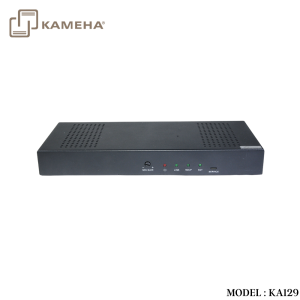
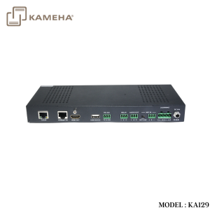
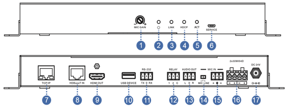
Receiver Panel
| Number | Name | Function description |
| 1 | MIC GAIN | Set the MIC input gain. |
| 2 | POWER LED | System power indicator. |
| 3 | LINK LED | HDBaseT Link status indicator.
▪ OFF: No Link. ▪ GREEN: Link successful. ▪ Blink GREEN: Link abnormal. |
| 4 | HDCP LED | HDCP compliance indicator.
▪ OFF: HDMI input is not carrying HDCP content. ▪ ON: HDMI input is carrying HDCP content. |
| 5 | ACT | System work indicator.
▪ OFF: System standby or power off. ▪ Blink GREEN: System working. |
| 6 | SERVICE | For firmware updated use. |
| 7 | TCP/IP | Connect to a PC access to the Web GUI for system setting. |
| 8 | HDBaset IN | Connect to HDBaseT Transmitter with a Cat5e/6/7 cable. |
| 9 | HDMI OUT | Connect to a HDMI display device. |
| 10 | USB DEVICE | Connect to an interactive display. |
| 11 | RS-232 | RS-232 control for the display. |
| 12 | RELAY | To control the projector screen rise and fall. |
| 13 | AUDIO OUT | Connect to a speaker. |
| 14 | MIC LINE
SWITCH |
▪ When the switch is set to “MIC”, the microphone input is used to connect a dynamic microphone.
▪ When the switch is set to “LINE”, the microphone input is used for connecting a line level audio source or wireless microphone output. |
| 15 | MIC IN | Using Phoenix terminal cable to connect microphone input. |
| 16 | 2X30 watts @4Ω | Connect to speaker out. |
| 17 | DC 24V | Connect 24V/3.75A adaptor to AC wall outlet for power supply. |
Application Example
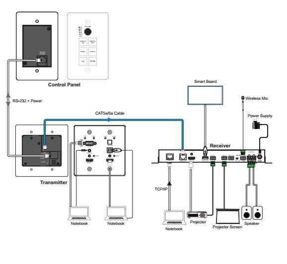
*** Control panel can be bought separately, model KA130
Additional information
| Weight | 2.1 kg |
|---|---|
| Dimensions | 30 × 27.5 × 11 cm |
| Warranty | 1 Year Warranty |
| What's in the box | 1* HDMI Extender Transmitter |
Related products


Splitter


Converter


