
Description
Introduction
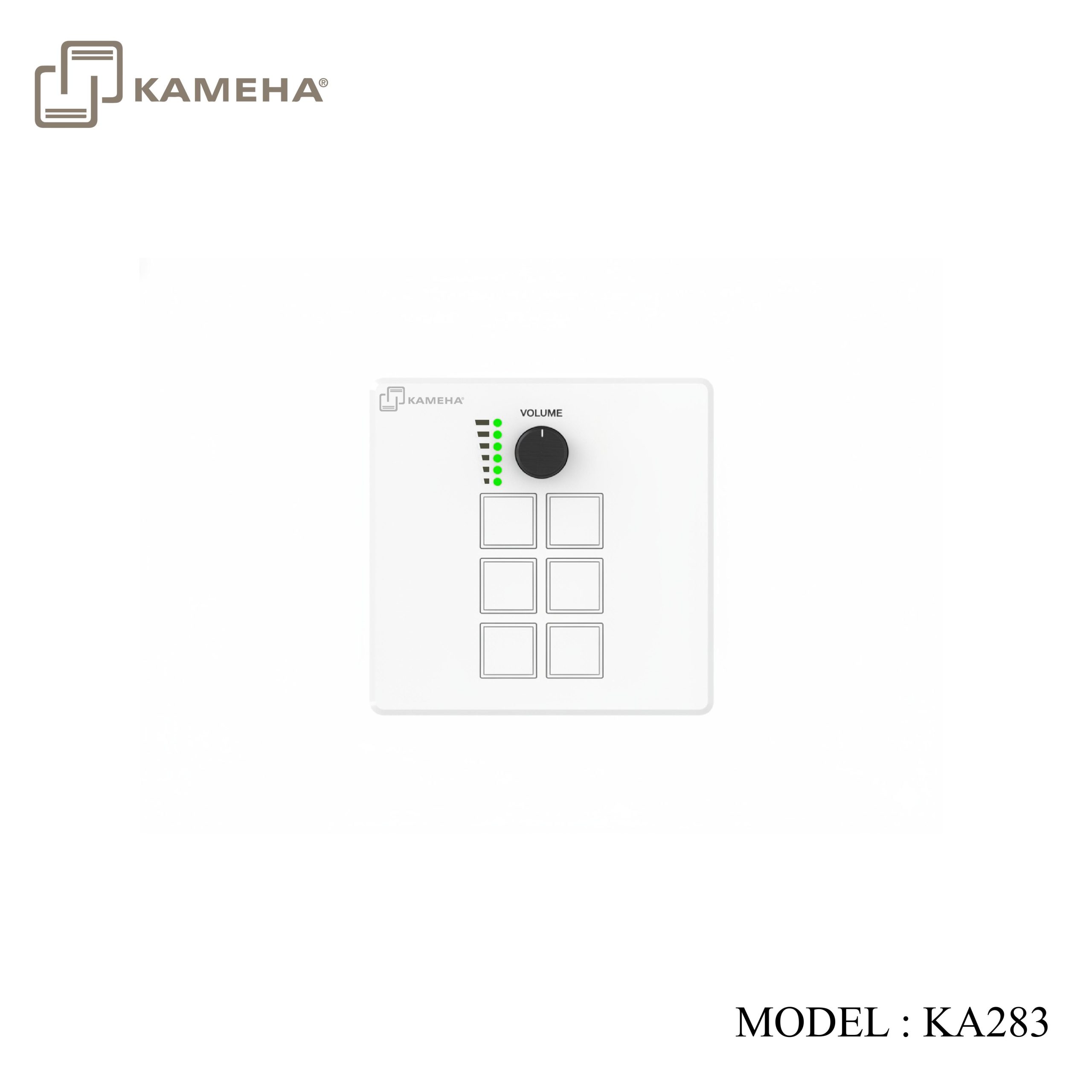
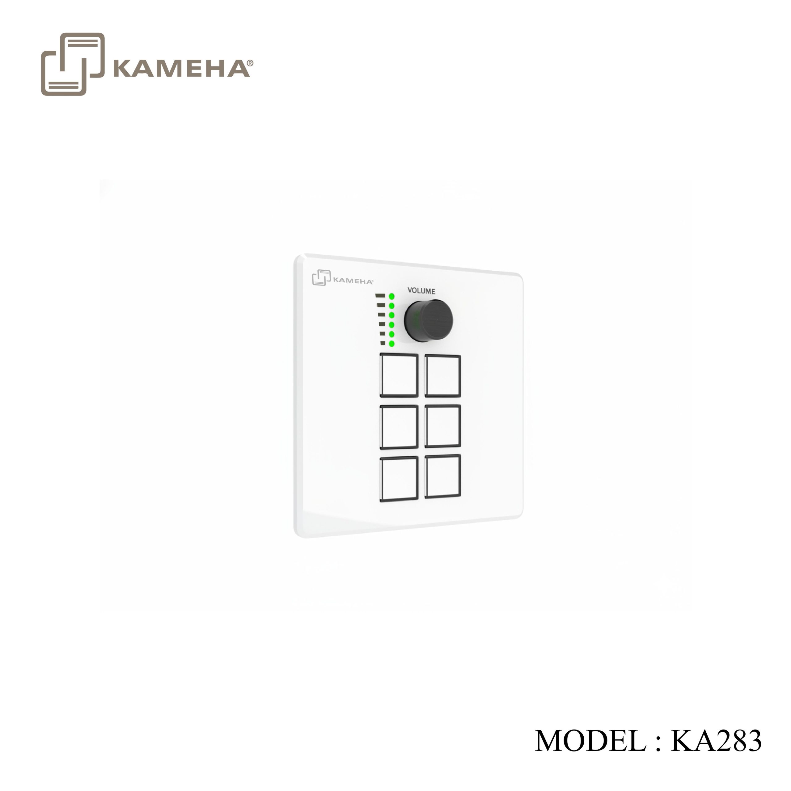
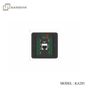
This intelligent control terminal is designed specifically for smart office and home scenarios, using an embedded wall mounting structure and compatible with EU/US/UK/CN standard cassette boxes. The control panel integrates 6 programmable buttons and 1 precision knob (with real-time numerical feedback function), equipped with RS232/RS485 serial port, IR remote control, relay signal and universal I/O ports, supporting universal network protocol. Through modular configuration management, cross device linkage control can be achieved, enabling the rapid construction of scenario-based solutions such as one click switching of projection modes in conference rooms, collaborative operation of training center equipment, or intelligent guidance of exhibition venues
Features
- ARM Cortex-A7 architecture 1.2Ghz main frequency
- Linux system, 256MB RAM, 256MB ROM
- Installation specifications: UK/CN 86 box/US 1-Gang/EU 2-Gang
- Magnetic aluminium panel design, beautiful and easy to replace
- 6 programmable buttons and 1 programmable knob, supporting light status feedback (with light indicators)
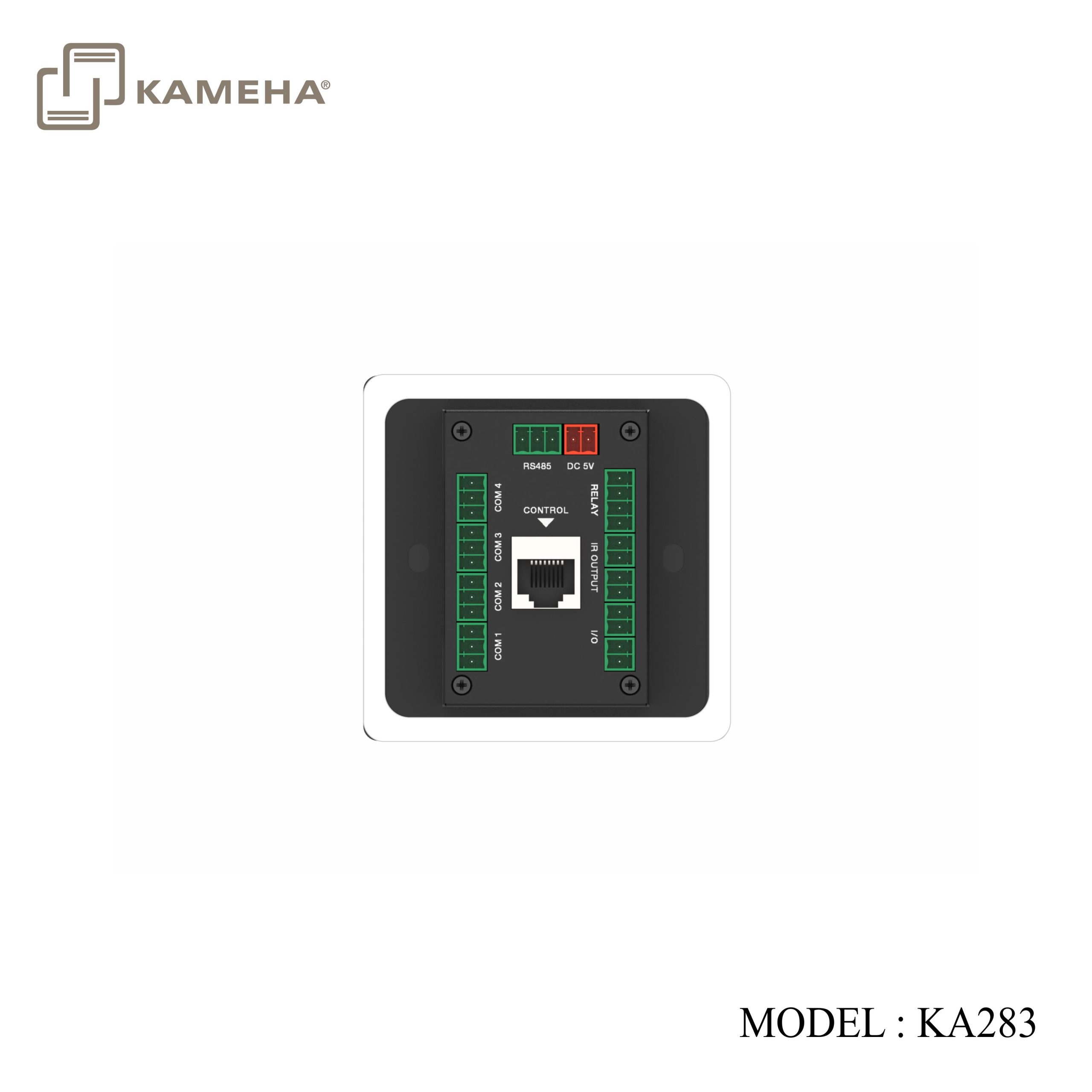
- 4-channel RS232 two-way serial communication ports, with configurable baud rate
- 1-channel RS485 serial communication port, with configurable baud rate
- 2-channel isolated low-voltage relay ports
- 2-channel I/O ports, with configurable input/output mode
- 2-channel IR output ports, supporting 20Khz-60Khz wideband output
- 1-channel 100Mbps network port, integrated with industry standard network communication protocols (TCP IP/UDP/HTTP/Websocket)
- Dual power supply mode, supporting PoE or DC power supply
Specifications
| Technical | |
| CPU | ARM Cortex-A7 1.2GHz |
| Operation System | Linux |
| RAM | 256MB |
| Flash Memory | 256MB |
| ESD Protection | IEC 61000-4-2:
±8kV (Air-gap discharge) & ±4kV (Contact discharge) |
| Connection | |
| COM 1/2/3/4 | 4× 3-pin phoenix connector, for RS232 serial data communication |
| RS485 | 1× 3-pin phoenix connector, for RS485 serial data communication |
| RELAY | 2× 2-pin phoenix connector, isolated low-voltage relay port |
| IR OUTPUT | 2× 2-pin phoenix connector, for IR signal output |
| I/O | 2× 2-pin phoenix connector, for I/O input and output |
| CONTROL | 1× 10M/100M Ethernet port, supporting PoE function |
| DC 5V | 1× 2-pin phoenix connector, for power supply |
| USB | 1× USB Type C port, for system debug |
| Mechanical | |
| Housing | Front Panel — Aluminum alloy; Rear Case — Metal enclosure |
| Color | Front Panel — Black/White (optional); Rear Case — Black |
| Dimension | EU: 146mm (W) × 85mm (H) × 38.5mm (D)
US: 70mm (W) × 114mm (H) × 38.5mm (D) UK/CN: 86mm (W) × 86mm (H) × 38.5mm (D) |
| Weight | EU: 287g; US: 227g; UK/CN: 218g |
| Power Supply | DC 5V/1A or PoE |
| Power
Consumption |
1.5W |
| Operation Temperature | 0°C ~ 40°C / 32°F ~ 104°F |
| Storage
Temperature |
-20°C ~ 60°C / -4°F ~ 140°F |
| Operation Humidity | 20%~80% (relative humidity, non-condensing) |
| Storage Humidity | 10%~90% (relative humidity, non-condensing) |
Operation Controls and Functions
| No. | Name | Function Description |
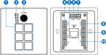
| 1 | 1~6 buttons | 6 programmable buttons, which can be flexibly configured according to application requirements. The button icon is made from film, which can be customized and replaced. |
| 2 | Knob LED (Green) | Knob progress LED, indicating the changes of the knob. |
| 3 | Knob | 1 programmable knob (with button function), which can be flexibly configured according to application requirements. |
| 4 | COM1/2/3/4
port |
4-channel programmable RS232 serial communication ports (3pin phoenix connector). It can be programmed to configure 8 baud rates in the range of 2400-115200bps. Pin definition: PIN1 is TXD, PIN2 is GND, and PIN3 is RXD. |
| 5 | CONTROL
port |
1 standard 10M/100M Ethernet RJ45 port, supporting PoE function. It is in automatic rate negotiation mode by default, mainly used for connecting devices, uploading/downloading projects, network communication, debugging, etc. By default, the DHCP function of the control panel is disabled, with IP address set to
192.168.0.101, and subnet mask set to 255. 255.0.0. |
| 6 | RS485
port |
1-channel programmable RS485 serial communication port (3pin phoenix connector). It can be programmed to configure 8 baud rates in the range of 2400-115200bps.
Pin definition: PIN1 is A, PIN2 is B, and PIN3 is GND. |
| 7 | DC 5V port | The power input port (2pin phoenix connector), used for connecting with external 5V DC power supply. |
| 8 | RELAY port | 2 sets of isolated low-voltage relay ports. Each relay is normally open, with a maximum load capacity of 2A 30VDC / 0.3A 125VAC. The ports do not support internal output voltage.
Pin definition: PIN1 is for signal input, and PIN2 is for signal output. |
| 9 | IR OUTPUT
port |
2-channel programmable IR ports, with a carrier range of 20KHz-60KHz for infrared output.
Pin definition: PIN1 is IR output, PIN2 is GND. |
| 10 | I/O port | 2-channel programmable I/O ports, configurable as input or output mode.
Input mode: Used to collect digital level signals, low level is effective, with port withstand voltage of 24V. Output mode: 5V level, maximum output 50mA current, with low level by default. Pin definition: PIN1 is I/O, PIN2 is GND. |
| 11 | RESET button
(behind the front panel) |
Reboot: After the device boots up, press and hold the RESET button for more than 1s less than 5s, then release it, the device will reboot. The device won’t upload the user projects after rebooting.
Reset: After the device boots up, press and hold the RESET button for more than 5s, then release it, the device will reset the user configuration information, the IP will be restored to the default settings (IP address: 192.168.0.101, subnet mask: 255.255.0.0), the login password of the management page will be initialized to “admin”, the device time will be initialized to automatic acquisition mode, but user projects won’t be deleted by factory initialization. |
| 12 | USB-C port (behind the front panel) | The reserved port for system debugging. |
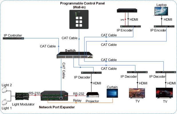
Application Example
Additional information
| Weight | 0.40 kg |
|---|---|
| Dimensions | 18.50 × 13.60 × 7.50 cm |
| WARRANTY | 1 YEAR WARRANTY |
| WHAT'S IN THE BOX | 1* 6-KEY ROTARY KNOB CONTROLLER |
Related products


